Introduction
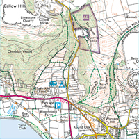
Contour lines are a way of representing height and structure on a flat map. In real life the landscape around you is full of (Three dimensional) features, rolling hills, sudden drops, gentle inclines, steep spurs and flat farmland. It is next to impossible to represent this directly onto a map (The major problem being that it is impractical. A map with fully featured bumps and lumps like those you may have seen in your school geography classes is a bugger to fold up!). In order to show this (very important!) information on the map we use contour lines.
Maps

Weatherproof, Tough & Durable, Anti-glare, Write on/Wipe off, Lightweight AQUA3®
Aqua 3 sell special all weather maps. These are coated with a special waterproof material and prove to be very useful in the poorest of weathers.
What are contour lines?
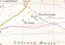
Well the trivial answer is that they are those faint brown lines all over your Ordnance Survey map.
What on Earth do they mean?
Contour lines are a way of representing height and structure on a flat map. In real life the landscape around you is full of (Three dimensional) features, rolling hills, sudden drops, gentle inclines, steep spurs and flat farmland. It is next to impossible to represent this directly onto a map (The major problem being that it is impractical. A map with fully featured bumps and lumps like those you may have seen in your school geography classes is a bugger to fold up!). In order to show this (very important!) information on the map we use contour lines.
Reproduced by kind permission of the Ordnance Survey. MC 99/91
A contour line represents a particular height above a fixed point (sea level) in metres. Every point on that contour line is at the same height above sea level. They therefore operate on a similar principle to Isobars and Isotherms in meteorology, where each line represents a particular pressure or temperature and each point on that same line has the same pressure/temperature.
You will find that not every contour line is marked with an actual value. On an Ordnance Survey Landranger 1:50 000 map, the contours are spaced at 10 metre intervals. Only a few contours are actually marked with a number.
Err, Right. So what good are they?
Contour lines are invaluable in certain situations. Walking, route planning, direction finding or position locating require a basic understanding of contour lines. With practice you can look at a map and envisage the landscape as it should appear in real life. At the very least you should be able to tell if you have to walk up a mountain or if it is flat ground all the way. By applying a few simple principles you can learn a lot about the 'lay of the land' from contour lines.
Slopes
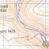
Perhaps the first thing you would want to know about that upcoming slope is just how steep is it? In maths we would call the steepness the gradient of the slope. Everyone has an intuitive understanding about steep/not steep but how do we work out the gradient from the map?
Let us first glance over a little definition of the gradient. The steepness of the slope is determined by how quickly you gain vertical height in terms of how far you walked horizontally during that time. If you ascend 3m in just a few strides you are certainly walking up a steep incline, one with a large gradient. If you have to walk several miles before you gain a few metres in vertical height the incline is very shallow, it has a small gradient.
If you really want an equation for this then (using the standard axes, horizontal - x and vertical - y)
Gradient = Change in y/Change in x
Now remember each contour line is associated with a particular height. If during your travels you cross 2 of these contour lines (recall they are space at 10 metre vertical height intervals, i.e. the next contour line is 10m higher than the previous one) then you will have ascended a vertical height of 20m. The steepness of the slope is determined by how quickly you gained this height. The 'further' you had to walk to cross 2 contour lines, the shallower the incline, the slope is not very steep. Now think about what this means on a map. The horizontal distance you are walking is represented by the distance you move across the map (use a ruler and compare it to the correct scale for the map). Please note, horizontal distance is what you are measuring with your ruler, not the actual distance in real life, and certainly misleading in terms of effort required. That is why contour lines are important in route planning.
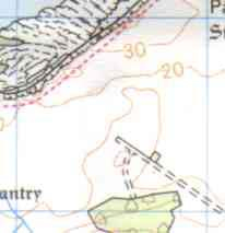
Now the more contour lines you cross in a set distance (say a kilometre) the steeper the slope. In other words, and this is the important bit;
The closer the contour lines are together, the steeper the slope
If you learn nothing else in this section, learn this. This is all you need to know to begin to 'picture' the landscape.
Convex Slopes
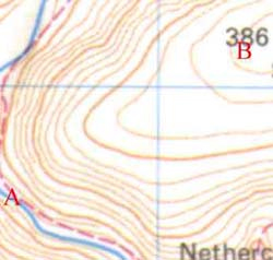
This is the opposite to a concave slope. The gradient increases as you 'walk downhill'. You can't quite see it on the map (my fault) but as you walk from A to B you are going up a hill. On the initial part of your journey the contour lines are closely packed, it is steep. As you reach the top of the hill the contour lines are spaced further apart, the slope is shallower, it is less steep.
Concave Slopes
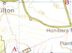
This is a slope that starts sloping downwards rather steeply, but flattens off the closer it gets to the ground. To remember which is which, think Concave - 'Caves in'. As you go from A to B the contour lines are getting further and further apart - the gradient is decreasing. It is getting less steep as you move down the hill.
Hill
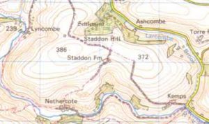
This set of contour lines represents a hill. The peak of the hill actually has a spot height of 386 marked upon it (just to the left of Staddon Fm marking). You can see that the contour lines form concentric 'circles' (complete loops of contour lines within another loop and so on). This is what defines the structure as a 'complete hill' rather than a slope or part of another feature. You may be able to see that the height of the hill varies from around 230m to 386m. Note also that the road and the river run around the base of the hill following the lowest contour line (the 'easiest' route).
Spot Heights & 'Road Gradients'
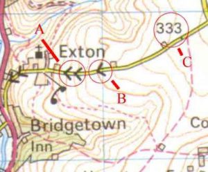
A spot height (C) does exactly what it says on the tin, it tells you the height above sea level at that particular spot. On the map it is simply a point with a number next to it. In real life it may even take the form of an actual post, similar to a milepost. Having spot heights on the map allows you to judge more accurately how the gradient is changing in between the contour lines.
A road gradient takes the form of either a single or double arrow marked in black on the road. These represent a gradient of 1 in 5 or steeper (A) and a gradient of between 1 in 5 - 1 in 7 (B) respectively. They are a way of showing 'sudden' changes in gradient along a road, a steeply dipping/climbing section of the road.
Contribution from Mark Lange (ACSL, 1st Mendlesham Cubs)
Idea 1: Demo how contours work with a cardboard hill.
I cut out a fairly large 'pacman' of cardboard (flat, I used a frozen pizza box, corrugated wouldn't bend properly), i.e. about a three-quarter circle, with hooked tabs on one straight edge and slots on the other. I then bent this round into a 'hill' and drew contours on it with a marker. I know that the contours aren't actually contours when it's folded out, but even so I think it helps to demo the 2D-3D transition. The more useful aspect though was being able to look at the hill from the side (I put it on the table) to see how the lines are parallel and horizontal, then look at it from above to see them as 'concentric'. It actually looked very similar to the diagrams on the first page of your mapping_contours_001.pdf sheet. I was careful to not have the 'pacman' actually circular, so one side was steeper than the other to show that. I also made a 'knoll' which I could add onto the side of the hill (smaller version with more tabs, and slots in the main hill) to show how more complex shapes show up on contours.
Idea 2: Make bas-relief faces of the Cubs
I couldn't think of a more immediate and personal way to make the function of contours visible, and it worked much better/easier than I had expected.
Drawing the contours: Set up a flat surface (table) suitable to lie on. Get a torch with an even spread of light (LED torches probably best). - attach some card stick to out the front of the torch to create a horizontal shadow line. - you may get a good enough shadow line with some torches just sat straight on the DVDs. Get a pile of DVD boxes or similar to set the height of the shadow. Get the subject to lie on their back on the table, set their head so their face is 'horizontal'. - they have to keep it that way until finished! Use a make-up pencil or thin face paint crayon to draw along the shadow line at each height interval. Take a front-on photo to show all the contours. - it may be clearer to use if you convert it to monochrome (black and white, not greyscale).
Making the relief face model: Print out and stick the photo to corrugated cardboard, with blue tack or something removable. Cut around the outermost contour line. Move the now smaller photo to a new piece of cardboard. - to increase the 3D relief effect, cut two or more pieces of card at each stage. Again cut around the next outermost contour (the one which hasn't been cut before). Repeat until all the contours have been cut, and you have no photo left. Stack up the card and stick together (double-sided tape might be best). - a second print-out of the photo might help with aligning the layers
Decorate! You could use papier-maché or similar to smooth over the face, although that would cover the visible contour layers.
Downloadable Guide
Downloadable Guide
Downloadable Guide
Grid References: 6 Figure and Bearings
Downloadable Guide
Downloadable Guide
Featured Resources
Be sure to check out the excellent resources provided by Graham from the 12th Andover West.
Downloadable Guide
Map Symbol Bingo (A4) by Graham Williams, 12th Andover West
Downloadable Guide
Map Symbol Bingo (A3) by Graham Williams, 12th Andover West
Downloadable Guide
Map Ready Reckoner by Graham Williams, 12th Andover West
